Note:
After getting the module, you need to connect the module to your own flight control with a wire, and then adjust the program with your head down.
You may need to use an electric soldering iron.
It is impossible to play with this module without a certain foundation of skills.
Kindly think it twice before you pay the order please!!
Feature:
1. size: 14x11x5mm Very tiny,only 0.6g, But the performance is very good,.Indoor normal lamplight also can be used on ceramic tile floor
2. No schematics! No source code! Don't open source!
Module interface and protocol:
This module sends data information to the computer through the serial port.
Data features:
A. 8-bit data bit, no check bit, 1-bit stop bit, baud rate set to 19200bps.
B. Data frequency: about 66fps frame rate to send data to the host.
C. Others: if the displacement of two consecutive frames is too small, 0 will be output, and then the data will be output when the displacement is enough.

Description:
A. Header is the fixed two bytes: OxFE (header), 0x04 (number of bytes);
B. DATAO, DATA1 is the low and high eight bits of flow-x, namely fow-x= (int16)(DATA1<<8) (DATA0) :
C. DATA2, DATA3 is the low and high eight bits of flow-y, that is, flow-y= (int(DATA3<<8)(DATA2);
D. The last but one byte is the check byte, which is the accumulated value of the four bytes of data0-data3, that is, SUM= DATAO+DATA1+DATA2+DATA3;Networking to identify and translate.
E. The penultimate byte is the ground environment quality;
F. The last byte is the packet end identifier, fixed as OXAA;
Testing:
Put it on the flight control first. This is how I connected it.
I used an electric soldering iron to weld three dupont wires to the module, and then directly plugged them into the serial port of flight control. Note: the input voltage is 3.3-3.6v. The voltage is too low for the module to work properly and may damage the module if it is too high.

first
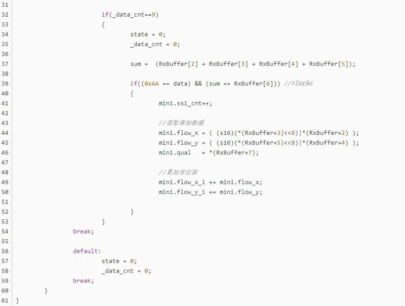
data receiving and parsing, this point is not detailed, according to the communication protocol to write code, relatively simple code directly on it.


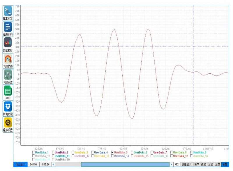
let's take a look at the original data curve of optical flow output. Test conditions: the module is about 20cm away from the desktop, the lens is facing the desktop, and the data output range is about +-30:

Second
Processing of optical flow data (since the data output by this optical flow has not undergone inertial fusion, it must be processed before it can be used).
In the first step, a simple low-pass filter is applied to the integral displacement.

Step 2, the integral displacement (#define angle_to_rad 0.0174f // arc) is compensated by the attitude Angle.

Note: 600.0f is an important parameter! Need to adjust slowly, adjust to how just calculate eligible?
When the plane is shaking in situ, pixel_flow.fix_x_i and pixel_flow.ang_x curves can be almost the same amplitude of change, the two offset each other to achieve the effect of compensation. Or to put it this way: pixel_flow.fix_y_i and pixel_flow.ang_y curves vary by almost the same amount (note in particular that the integral displacement data will slowly increase or decrease when the plane is rolling in place, which is the phenomenon of integral drift and is normal).
Curve of pixel_flow.fix_x_i and pixel_flow.ang_x when the plane is shaking in place:

Step 3, the integral displacement is differentiated to obtain the velocity.1

Now, some people might be confused by this, why do we differentiate the velocity instead of just using the output of the optical flow as the velocity? The reason is that the output data of this optical flow module is not strictly speaking the speed, but the relative displacement of two consecutive frames in pixels.
The curve of the plane's speed as it moves back and forth in a horizontal plane:

The purpose of compensating integral displacement with attitude Angle is to keep integral displacement as constant as possible when the plane is shaking in situ. Why do we want to keep the integral displacement as constant as possible? Quite simply, because the plane is shaking in place, the displacement is not changing.
When the plane is shaking in situ, the integral displacement curve after attitude Angle compensation is shown as follows:

Step 4. Convert the data units to centimeters.

At this point, the processing of optical flow data is basically completed. With the two parameters of integral displacement and differential speed, cascade PID control of position loop and speed loop in the horizontal plane can be carried out.
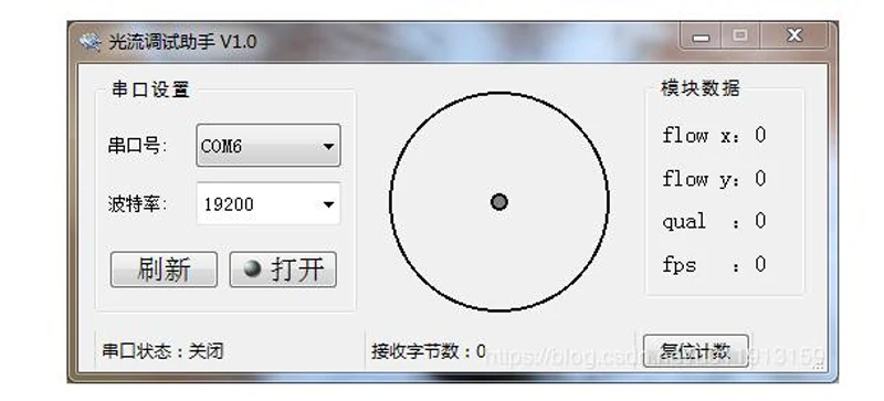
Finally, I will provide you with an optical flow debugging assistant. After connecting the mini optical flow module to the computer through the serial port module, you can open the upper computer to view the optical flow module data and have the function of dynamic display, which is very convenient! The communication protocol is consistent with that described in this article.


